The Open Systems Interconnection (OSI) model is a series of layers that computer systems use to communicate. There are seven layers, and the networking layer would be layer 3. The network layer is responsible for packet forwarding, including routing through intermediate routers. However, when it comes to understanding network data delivery, we need to get through layer 2 before we can move on to layer 3.
The data link layer, or layer 2, is the protocol layer that transfers data between nodes on a network segment across the physical layer, or what is commonly known as a host’s physical address. Layer 2 is divided into two parts, consisting of the MAC and data link sublayers, detailing addressing and the layout of data frames, and Layer 3 includes a host’s logical address. Let’s take a closer look at how these layers work together to ensure a delicious flow of data.
What are the seven layers of the OSI model?
Before we dig deep into layers 2 and 3, let’s start with a little bit of background on the Open Systems Interconnection (OSI) model. The OSI model was developed by the International Organization for Standardization (ISO). It describes the layers that computer systems use to communicate over a network and was the first standard model for network communications adopted by all major computer and telecommunication companies in the early 1980s.
The OSI model has seven layers:
- Physical
- Data Link
- Network
- Transport
- Session
- Presentation
- Application
What is layer 2 in the OSI model?
As mentioned above, layer 2 is split into two parts: the media access control (MAC) sublayer and the data link sublayer. These sublayers each contribute to the computer’s physical address.
Media Address Control (MAC) sub layer
It is helpful to present an example that is familiar and easy to understand to gain an appreciation of the characteristics of addressing.
Let’s consider this in terms of a mobile home community. Each mobile home has a serial number permanently attached to the home’s frame. Computers have a similar address, called their media access control (MAC) address. That address is “burnt” onto the computer's network interface card and is unique in nature. An example of the MAC address is shown in Figure 1 below.
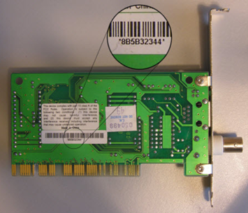
Figure 1: Media Access Control (MAC) address
MAC (or physical) addressing provides an effective method of moving data across a small community of computing devices where routing traffic between multiple communities is not required. Traffic distribution for these small networks is handled by layer 2 switches that learn the MAC addresses of the computers connected to ports on the switch. The switches then send packets from the sending computer directly to the receiving device. This method of directing traffic helps reduce potential network congestion.
A MAC address consists of a series of 12 hexadecimal numbers. The first six numbers are useful in identifying the network interface card manufacturer. The last six numbers are assigned by the card manufacturer, providing a unique addressing scheme. This avoids the possibility of having two computers on the same network with the same physical address.
Data link sub-layer
Another layer 2 function is to establish protocols related to the structure of data frames placed on the network for data transmission. Uniformity is an important characteristic, and this includes placing both addresses for the data sender and the data recipient. Figure 2 below provides an example of an Ethernet II frame.
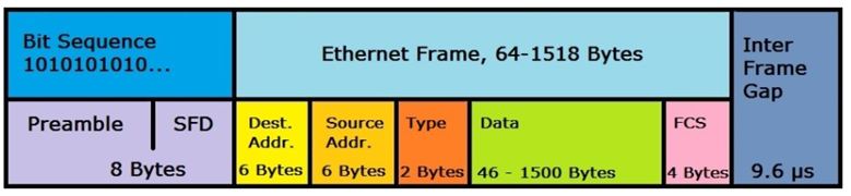
Figure 2: Ethernet II frame
Each frame includes the MAC address of the source of the frame and the MAC address of the intended recipient. When a device sends a packet to the broadcast MAC address (FF:FF:FF:FF:FF:FF), it is delivered to all stations on the local network.
MAC addressing worked well in the early days of networks, with only a few computing devices on a single flat network. Because of this, it was unnecessary to extend the network past its limited physical boundaries. A process associated with linking a computing device name to its MAC address, either by way of a table or through broadcast protocols like Microsoft’s NetBEUI, enabled devices to communicate effectively.
However, as networks grew, network traffic grew, and traffic congestion became problematic. As a consequence, a second layer of addressing designed to facilitate connecting two or more networks became necessary to deal with both traffic congestion and latency issues. Thus, the data link sublayer was born.
Understanding OSI layer 3
Commonly referred to as the networking layer of the OSI model, layer 3 provides the structure for efficiently transferring data from one network to another. Let’s return to the mobile home community example.
When a unit is placed in a mobile home community, it is typically located on a lot (often referred to as a space). The lot address can be used for postal service purposes. As you know, if you want to mail a package from one mobile home to another, serial numbers won’t work. But if you address the package properly, using the format the postal service requires, we have some assurance of delivery.
When it comes to computer networking, our postal service consists of computing devices known as routers. Functioning at layer 3 requires the creation of an outside envelope over the layer 2 frame that includes the layer 3 address of the packet sender and the layer 3 address of the recipient.
Layer 3 addresses are divided in a fashion that identifies a specific network address and a specific host or group of hosts. When it is determined that the recipient’s network address is different from the sender’s network address, packets are directed to the network’s router for delivery handling.
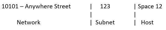
In today’s modern networking, we use the TCP/IP suite of protocols for communication that crosses networks. The postal service provides a vehicle for understanding how logical addressing using IP protocol works.
Using the logic address above, the postal service would be able to deliver a package based on the following:
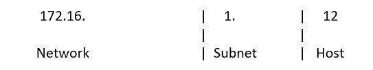
Using the IP (version 4) addressing scheme for the IP address 172.16.1.12/24, the address breaks out as:
The processes and procedures associated with logical networking, specifically subnetting and supernetting, are beyond the scope of this article.
It is important to understand that a portion of an IP address is allocated for both network and host identification. Devices located on the same network will be able to communicate effectively at layer 2. Devices on different networks will communicate by directing their output data to routers that will be charged with the responsibility of delivery.
Get started with CompTIA Network+
If computer networking piques your interest, CompTIA Network+ can help you develop your IT career. CompTIA Network+ certification holders are often hired as network field technicians, engineers, analysts, and support specialists – just to name a few.
Technology employers hire IT pros with CompTIA Network+ because the credential ensures you have the knowledge and skills to do the following:
- Design and implement functional networks
- Configure, manage, and maintain essential network devices
- Use devices such as switches and routers to segment network traffic and create resilient networks
- Identify benefits and drawbacks of existing network configurations
- Implement network security, standards, and protocols
- Troubleshoot network problems
- Support the creation of virtualized networks
There are various ways to start studying for CompTIA Network+, including self-study eLearning with CertMaster Learn or Certmaster Labs.
Want to start a career in computer networking? CompTIA Network+ can help you get there.
Steve Linthicum taught cybersecurity courses for decades as a professor at the college and university levels. He holds an array of IT and cybersecurity industry certifications.